Introduction
The thought of programming a project can be intimidating if it is the first time or if it's been a while since attending training. But in reality, Intelli-Site has been written to make project programming simple, straightforward, and elegant. This article will walk you through System Layout, adding Areas, adding RTUs, creating door constructs, and programming two simple screens. The replication wizard and the door construct auto-creation method will be used to enhance the speed and ease of programming. We will use a simple jail with an office area and a single pod of eight (8) cells as our example.
Procedure
Forethought and planning before beginning the project programming will make the process smoother. It is important to fully understand the facility that will be managed by Intelli-Site. It's important to know what equipment will be integrated with Intelli-Site, where it is located, and how it will be used. Consider how the user will monitor the system in Run Mode. Spend a few moments thinking about how to best organize and name the RTUs in the Project Tree.
The general process is:
- Add Areas and rename them to correspond to the areas being managed (such as Floor 1, Floor 2, Floor 3, or West Tower, South Tower)
- Add all of the hardware (RTUs) that will be integrated by Intelli-Site, organizing the hardware by area
- Rename all of the RTUs and their component parts appropriately
- Create Door Constructs for the doors and door-like elements
- Design screens that graphically represent the facility. These screens will use an image of the facility as the background. The Door Constructs will be used to create screen objects for the doors and door-like elements.
Note: It is important to name the RTUs and their components before creating door constructs because the names within the RTUs are automatically used when the door constructs are created. Changing the names on the RTU after the door constructs are created will not affect the constructs at all, meaning they will have to be modified by hand which can be a tedious process.
Before project programming, you will need:
- A list of all the hardware that will be integrated with Intelli-Site and their locations This list should include all of the configuration information. See the RTU Guides for the specifics.
- At least one image for the installation This can be a line drawing, a photo, or even a CAD drawing. All that matters is that it is an image that easily depicts the facility. It may be useful to have multiple images. (e.g., an office building may want an image per floor, a jail may want an image per pod)
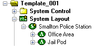
In Design Mode, expanding the System Layout node reveals the Corporate Headquarters node. Expanding the Corporate Headquarters node reveals an Area node. These are sample nodes. The Corporate Headquarters node would be the name of the facility, organization, or company for which the project is being programmed. In our example project, this is the Smallton Police Station. The Area node is a logical location to group RTUs. Quite often an area is a physical location for the installation. If the installation is a multi-story office building, an area could be one of the floors of the building. If the installation is jail, each pod of cells could be a different area. There is no best way to organize the RTUs. Keep in mind the people that will be using the system once it is programmed. They will need to be able to find a specific RTU with minimal effort. The more descriptive the names the better. Instead of naming a MAC panel MAC-4R 001, name it based on its function, Floor 1 Access Panel, or possibly an inventory designation. What is important is that the user will be able to find the node that corresponds to the piece of hardware with minimal effort.

Project Programming Process
Add Areas and Rename Them
- Add Area nodes so that there is an area node for each of the logical areas of your installation. To add an area, right-click on the Corporate Headquarters node and select "Add Node...". A new area node will appear under the target node.
- Rename the Corporate Headquarters and Area nodes appropriately. For our example of the Smallton Police Station, we have two areas: Office Area and Jail Pod.
Add RTUs to the Areas
- Add the appropriate RTUs to the various areas. To add an RTU to an area, right-click on the area and select "Add Node...". The Add Node dialog will appear.
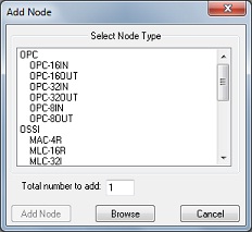
- Locate the desired RTU type from the Select Node Type list and click on it to select it. Enter the number of RTUs of the selected type in the Total number to add field. Then click [Add Node]. This button becomes active when an RTU type is selected.
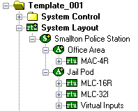
In our example, there is a MAC-4R access control panel that controls the doors in the Office Area. In the Jail Pod, the doors are controlled and monitored by an MLC-16R, and an MLC-32I. For the door constructs, we will create for the cell doors, we need a set of Virtual Points.
Rename the RTUs and Their Component Parts Appropriately
- Change the names of the RTUs so that the user can easily locate the correct node when necessary. As stated previously, there is no one correct way to do this. It really depends on the facility and the users.
- Change the names for sub-nodes of the RTU as needed.
- For an access control panel, the doors should be renamed.
- For other RTUs, some of the points may have special purposes. Case in point, the jail cell doors in our example are controlled via MLC-16R Outputs and MLC-32I Inputs. These points have generic names in the RTU which should be changed to reflect their usage.
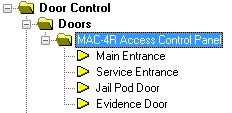
Rename Access Control Panel Doors
In our example, the Office Area has a MAC-4R that controls four (4) doors. The default names for those doors are Door 1 Reader, Door 2 Reader, Door 3 Reader, and Door 4 Reader. These names are not very helpful. They should be changed. When a door reader is renamed, Intelli-Site will ask if the name change should be propagated to the sub-nodes and I/O Points. It is a good idea to let Intelli-Site do this.
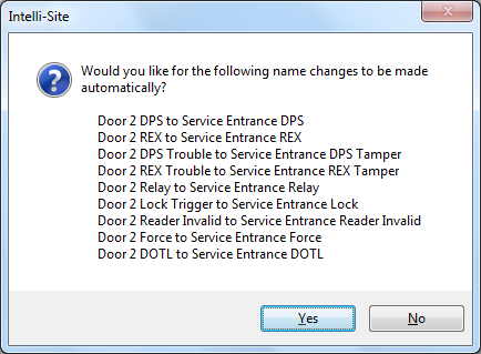
The door readers have been renamed Main Entrance, Service Entrance, Jail Pod Door, and Evidence Door.
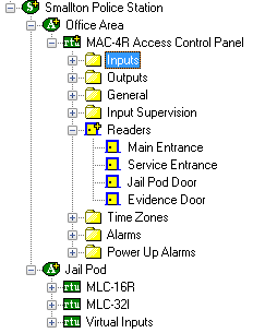
If you are curious, you can expand Inputs, Outputs, General, and Alarms to confirm that Intelli-Site has indeed renamed the I/O Points to reflect the new door names.
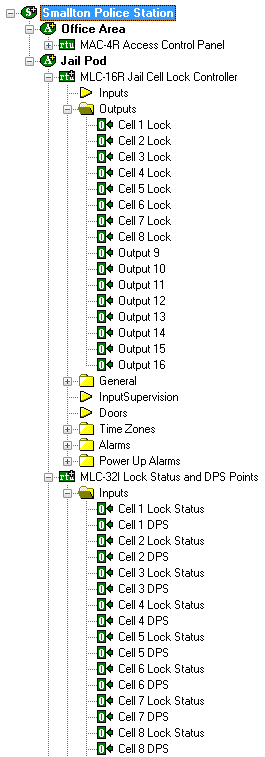
Rename the Points on the MLC-16R, MLC-32I
The Jail Pod area has an MLC-16R and MLC32I to provide the necessary controls for the jail doors. Eight (8) of the outputs on the MLC-16R have been wired to control the jail door locks. Eight MLC-32I Inputs have been connected to the door position switches (DPSs) for the jail doors. Eight more inputs have been wired to provide the status of the door lock. By default, the outputs are name Output 1, Output 2, etc. The inputs are similarly named. Again, the default names are not very helpful. They should be renamed to reflect their use.
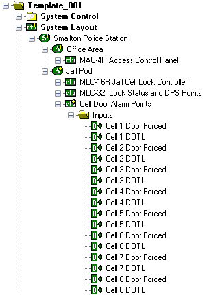
Rename Virtual Points
We need points that the Server will set for two alarm conditions for the cell doors in the jail pod. That is why we added the Virtual Inputs RTU. These two alarms are Door Forced and Door Open Too Long (DOTL). Rename the virtual points accordingly.
Create Door Constructs for the Doors and Door-Like Elements
Expanding the Door Control node reveals several sub-nodes: Doors, Zones, Interlocks, Call Stations, and Alarm Zones. Each of these is a different flavor of door control. The one we are most interested in is Doors. It's here that Door Constructs are created. The Door Construct feature of Intelli-Site provides a central configuration point for doors and door-like elements. An in-depth discussion of Door Controls and the Door Construct is the subject of another article. Here we will only show how to use door constructs.
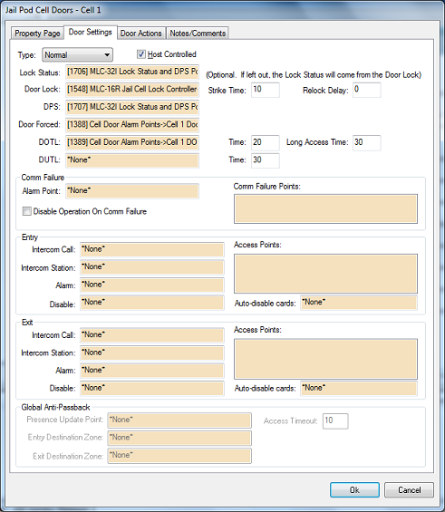
The figure below is the Door Settings tab of door construct properties.
![]()
As you can see there are quite a few fields involved in programming a door. Luckily, Intelli-Site can create door constructs automatically for those elements that are truly doors using drag and drop. Just drag and drop the access control panel onto the Doors node and Intelli-Site will create a door group of door constructs. There will be a door construct for each of the doors of the access control panel.
To make it easier to see both the Door Control nodes and the System Layout nodes, make a popup tree view of the System Layout node. Right-click on System Layout and select "Create Popup Tree View...".
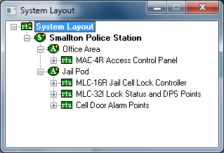
This window can be stretched like any other window. And when the nodes are expanded, the window can be scrolled through as well. Nodes can be dragged to and from popup tree views to other popup tree views and to the main Project Tree. There is no limit to the number of popup tree views. If you felt so inclined you could have a popup tree view open for every node in the Tree.
Creating Door Constructs from Access Control Panels
In our example, the MAC-4R Access Control Panel has doors.
- Drag this access control panel node from the popup tree view and drop it on the Doors node in the Tree.
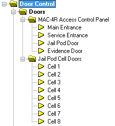
- When the node is dropped, Intelli-Site asks you to confirm that you want to create the Door Group. Click [Yes]. A door group named "MAC-4R Access Control Panel" is created. Expanding this node reveals the door constructs for each of the doors that this panel control
Notice that the door group has the same name as the access control panel and that the door constructs have the same names as the doors. This is another reason why it was important to name the RTU nodes and their sub-nodes.
- Drag and drop every access control panel in your project onto the Doors node. A different door group will be created for each panel. Each group has the same name as the node that was dropped.
Creating Door Constructs in the Absence of an Access Control Panel
Now let's turn our attention to the jail pod. Each cell has a door, but they are not controlled by an access control panel. So we can't just drag and drop the access control panel to create a door construct, but we still want to use a door construct to handle these doors. We have to create the door constructs by hand.
Before creating a door construct, there must be a door group.
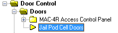
- Right-click on the Doors node and select "Add Node and Edit...". The new door group node is created and the properties are opened for editing.
- Change of the door group to express the purpose of this door group. In our example, the door group is named "Jail Pod Cell Doors".
- Click [Ok]
Now that we have the door group, we can add door constructs.
- Right-click on the door group and select "Add Node and Edit...". A new door construct is added to the door group and the properties are opened for editing.
- Change the name of the door construct to match the real door. We shall call it "Cell 1".
- Switch to the Door Settings tab. While this tab has a lot of fields on it, all we really care about are "Host Controlled", "Lock Status", "Door Lock", "DPS", "Door Forced", and "DOTL". These are the minimum fields for a door construct.
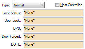
Remember that "Lock Status" and "DPS" are inputs, they come from the door into the MLC-32I, the "Door Lock" is an output of the MLC-16R, and the two alarms, "Door Forced" and "DOTL", are Virtual Points.
- Check "Host Controlled". The means the Server will be controlling the door. If there was an access control panel for the door, the access panel would control it. There isn't, so the Server must control it.
Note: The MAC panels can be programmed via ladder logic to control the cell doors instead of making them Host Controlled doors. But the purpose of this article is NOT ladder logic. Ladder logic is a feature of the MAC panel specifically. This article's purpose is to share information about features of Intelli-Site that can be used on the majority of projects no matter the hardware involved.
- Drag and drop the Lock Status and DPS inputs for this cell
- Drag and drop the Door Lock output for this cell
- Drag and drop the Door Forced and DOTL virtual points
Repeat for each of the cell doors.
When all the door constructs have been added, the Tree for the example project looks like this.
Design screens that graphically represent the facility
Now that we have our door constructs created, it's time to build the Run Mode screens that will let the user control the physical doors using these door constructs. For our example project, we have two areas, the Office Area and the Jail Pod. We can either have one big map with both areas or two maps. We are opting for two maps which means two screens.
Before an image can be used, it has to be imported into Intelli-Site.
Importing an Image into Intelli-Site
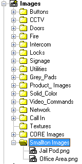
All of the images Intelli-Site uses can be found under the Images node in the Tree. Expanding the Images node reveals a number of sub-nodes, folders that contain the image files. The physical files reside on the Server. That way when a remote Workstation logs in, the Server gives the images as needed to the Workstation. The Workstation doesn't need to keep copies of the files to work.
- Add a sub-node to the Images node for custom images by right-clicking on the Images node and selecting "Add Node and Edit.." The new folder is created and opened for editing.
- Name the new node appropriately. Custom Images would work but in our case, we named it "Smallton Images"
- Click [Ok]
- Right-click on the new folder and select "Import...". The images have to be imported from wherever they exist into the Server.
- Locate and select the image(s) to import. Use the standard shift+click or ctrl+click methods to select multiple images.
- Click [Open].
The selected image files are now imported into the server and appear in the Tree under the new folder.
Create the Office Area Screen and Set the Background Image
The first thing we'll do is create the blank screen and add the background image of the floor plan.
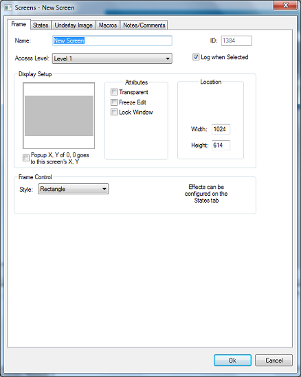
- Right-click on the Screens node and select "Add Node and Edit..." The new Screen is added to the Tree and the properties are opened for editing.
- Change the name of the new Screen.
Change the name of the screen.
Click on the States tab. Locate the Images field.
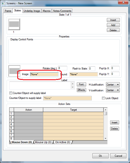
- Drag and drop the image to use as the background for this screen. This should be one of the site maps. Since this screen is going to be the Office Area, the map image for the office area will be dragged here. Notice that the dropped image is displayed on the grey box next to the Image field and again on the state box at the top of the page.
- Click [Ok] to save the changes.
Add the Door Screen Objects to the Office Area Screen
We are now ready to add the door screen objects to the screen using the door constructs. These door screen objects have six (6) states. The first state is the normal state. The door is in the proper position and there are no alarms associated with the door. There are other states to indicate that the door is unlocked, DOTL, Forced, or the DPS is open. Each state may or may not have actions that are performed when the screen object is clicked. What is done depends on the state of the door screen object. The behavior of the door screen object is the subject of another article. Suffice it to say that the standard programming of the door screen object fits the needs of 99% of all installations that use them.
To add the door screen objects, do the following:
- In the Tree, expose the door constructs that will be used on this screen.
- Drag and drop the first door construct onto this screen. It must be the first so we can take advantage of the Replicate feature of Intelli-Site. When the door construct is dropped, a Customize New Object dialog appears. Just click [Ok]. A new object appears on the screen and in the Tree. It has the same name as the door construct and that name appears as the label on the new screen object.
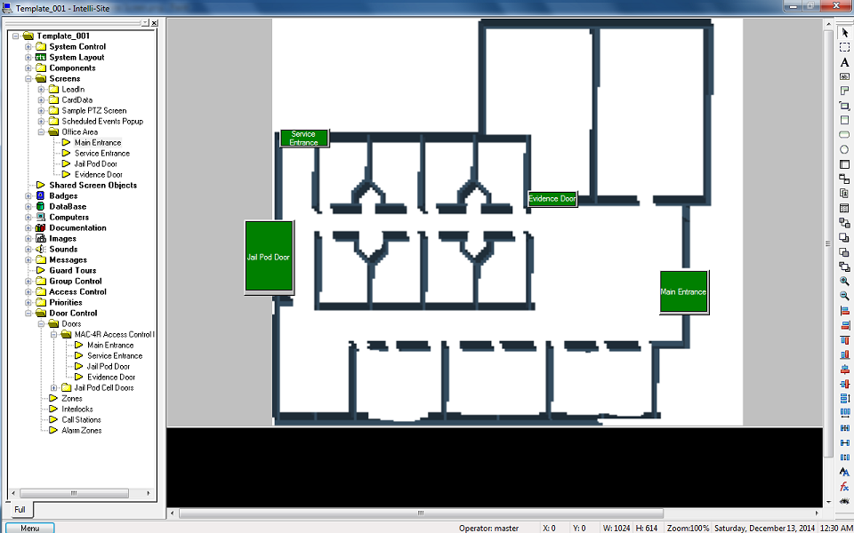
- Locate the door screen object in the Tree. It will be under the Screens node and the screen that is being created. In this case, the Main Entrance node is under Screens->Office Area
- Right-click on this node and select "Replicate..." The Replicate Object dialog displays.
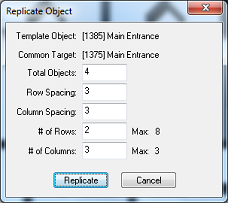
Intelli-Site locates the object in the Tree and makes an educated guess as to the number of total objects to create based on the nodes following the targeted object. In this case, there are four (4) door construct objects including the target.
- Click [Replicate]. Intelli-Site creates door screen objects for each of the other doors.
- Move these new door screen objects to their desired locations.
Create the Jail Pod Screen
The jail pod screen is created following the same steps used in creating the Office Area screen. Only this time, for the purposes of the example, we are going to customize the door screen object before it's replicated.
- Add a new screen to the Screens node as before. Change its name and add the background image.
- Double-click the new screen to display and edit it.
- Drag and drop the first of the cell door constructs onto the screen.
- In the Customize New Object dialog, click the "Replace default images with those from this folder." radio button.
- Expand the Images node in the Tree. Expand the Doors node as well. Here you find a number of folders containing different door images. Drag and drop one of these folders to the drag and drop target field in the Customize New Object dialog and click [Ok]. The new screen object is created using the images from this folder instead of the default images.
- Select the screen object and adjust the size and appearance until you are satisfied with it.
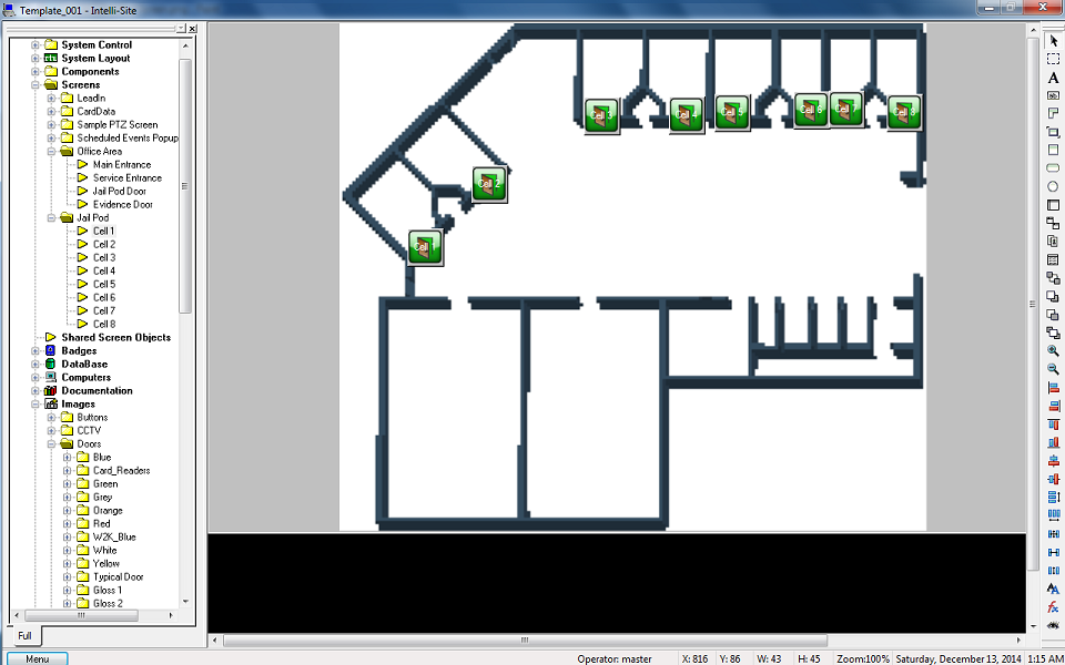
- Locate the door screen object in the Tree. Right-click on it and select "Replicate...". The Replicate Object dialog displays. In the example project, there are eight (8) jail cell door constructs. Intelli-Site detects this since we used the first door construct to create the door screen object.
- Click [Replicate]. Intelli-Site creates the rest of the jail cell door screen objects using the replicate target as the source of the formatting information.
- Move the screen objects to their desired locations on the map.
Finishing Touches
All that is left are the finishing touches. Just because these screens have been created, doesn't mean these screens will ever display. Buttons need to be created and programmed and placed so that the screens can be reached. Navigation buttons are a good candidate for Shared Screen Objects. Quite often they are used on more than one screen. As a shared screen object, the programming is done once and used in multiple areas. We will create two buttons, one to display the Jail Pod screen and the other to display the Office Area screen.
- Right-click on the Shared Screen Objects node and select "Add Node and Edit.." A Shared Screen Object Group node is added to the Tree and opened for editing.
- Change the name of the resulting node. We call it "Navigation Buttons" since the buttons for navigating through the screens will be added to it.
- Click [Ok]
- Right-click on this new node and select "Add Node and Edit...". A Shared Screen Object node is added to the Tree and opened for editing. This is object will be one of the navigation buttons.
- Change the name to reflect its operation. We called it "Display Jail Pod Button".
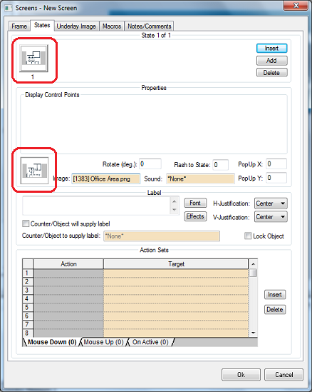
- Switch to the States tab
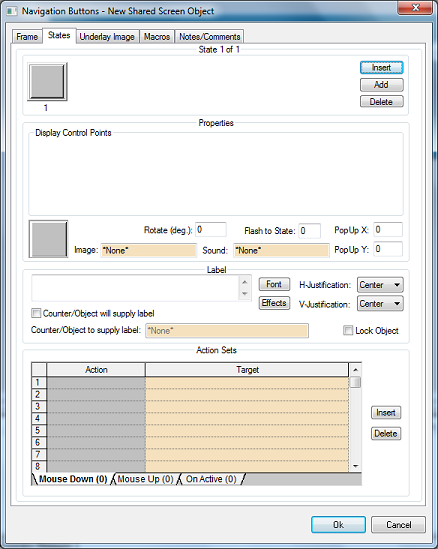
The States tab is where the look and feel of the screen object are set. More importantly, here is where the actions are defined that will be executed when the screen object is clicked.
- Click the check box next to "Counter/Object will supply label".
- Drag and drop the target screen node into the "Counter/object to supply label:" drag and drop box.
- In the action grid, click on the first rectangle under the Actions column. The Actions dialog displays.
- Locate the Screen Control group.
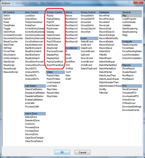
- Select "Display" and click [OK] or double-click "Display". The dialog disappears and the Display action is written into the Action column.
- Drag the target screen node into the Target column.
This is all that actually has to be done, but it can be frustrating to click on an object and not know if the click was successful. It is a good idea to give the user feedback. One way to do so is to have an action to play a sound like a click.
- In the action grid, click on the second rectangle under the Actions column. The Actions dialog displays.
- Locate the General group and select Play.
- Expand the Sounds node in the Tree. Expand the Selections node. Locate the Click.wav.
- Drag and drop the Click.wav into the Target field for the second row of the action grid
- Click [Ok] to save the changes.
The button may not be the correct size. To change the size of the button, you must edit the shared screen object.
- Double click on the shared screen object to display it to the right, ready for editing.
- Click on the screen object to the right and resize it.
At this point, you can create the second shared screen object to bring up the other screen when it is clicked, or we can copy and reprogram it.
Copy and Reprogram the Shared Screen Object
While holding down the Ctrl key, drag the shared screen object to its parent node and drop it. The Replace Programming wizard appears.
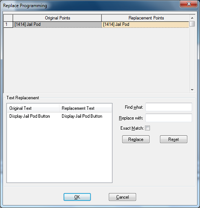
Note: If Intelli-Site prompts to "Continue with Move?", click [No] because the copy was unsuccessful. Try again. Make sure to hold down the Ctrl key and then hold down the right mouse button.
- Drag and drop the screen onto the first screen node in the Replacement Points table.
- In the "Find what:" field, type the name of the old screen.
- In the "Replace with:" field, type the name of the new screen.
- Click [OK]
There are now two shared screen objects, one for each screen.
Add the Screen Buttons to the Screens
Let's add the shared screen objects to the various screens. We will add both buttons to the Lead-In screen and one to each of the other screens.
- Double-click on the Lead-In screen
- Drag and drop both of the shared screen objects onto the screen.
- Double click on the first custom screen. The Office Area screen is the first of the example screens.
- Drag the correct shared screen object to the custom screen. The Jail Pod shared screen object goes on the Office Area screen.
- Double click on the second custom screen. This would be the Jail Pod screen.
- Drag the correct shared screen object to the screen. This would be the Office Area shared screen object.